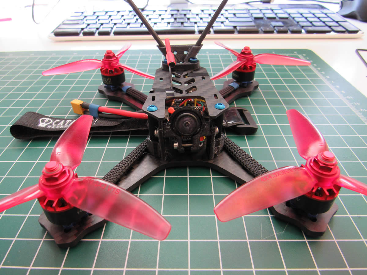
Here are some basic instructions and images I put together throughout my Catalyst Machineworks Superlight 4R build. I have thus far only done two test flights, but will report back on how fast this thing goes once I get to some real flight testing. I am hoping for 80mph+ speeds. These instructions will help you to build your own FPV quadcopter from scratch, regardless of the type of frame. I will try to fill in more detailed instructions down the road, but these basic instructions will help you to build your own FPV quadcopter. Happy Racing!
Huge shout out to Catalyst Machineworks despite a small hiccup concerning some missing pieces in my frame kit. They more than made up for it. Their customer service is top notch. I have an email thread going with them and they respond very quickly to my questions and queries. I will be buying the majority of my FPV Quadcopter parts from CM from this point on. I am 100% satisfied with what they have going on down in Texas!
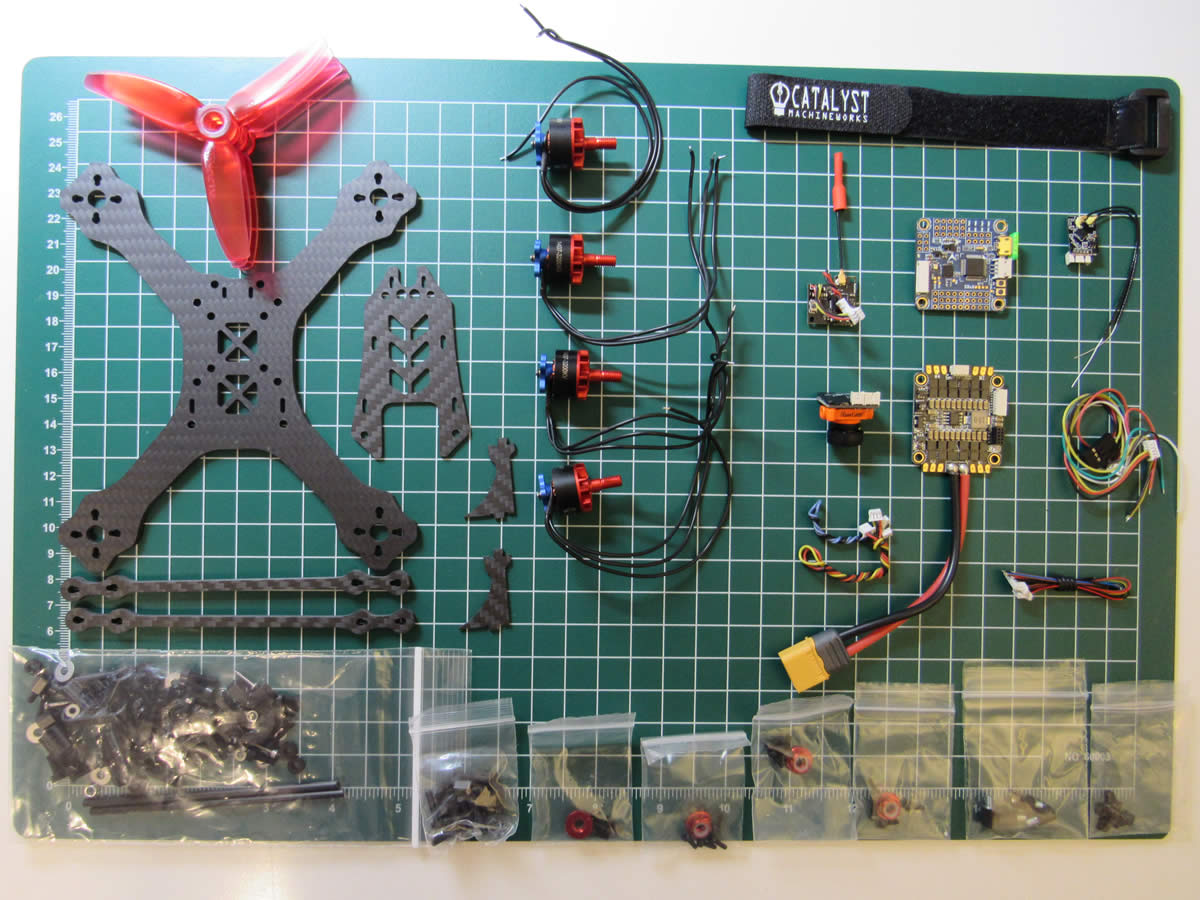
Parts List:
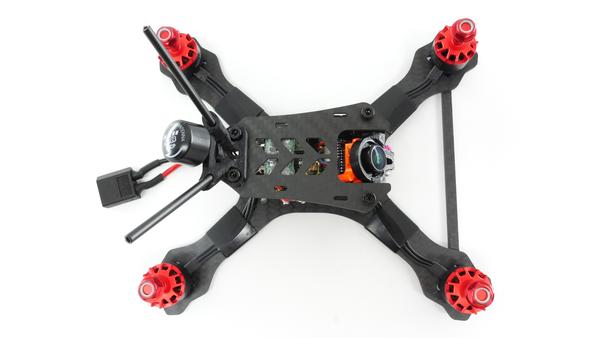
- 3.5mm carbon fiber frame
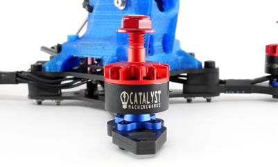
- 4 X 1407-3600KV motors
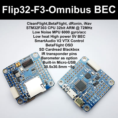
- Flip32 Omnibus F4 flight controller
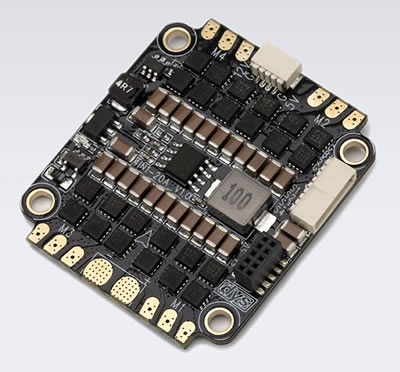
- 4 in 1 20A speed controller
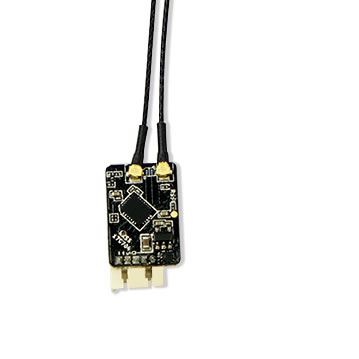
- FrDky XSR Receiver
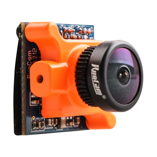
- RunCam Micro Sparrow 16:9
- RunCam TX200TX
- HQ 4X4.3X3 tri-blade props
Spec List:
- Betaflight with OSD
- DShot
- Gyro Filtering Mod


Under no circumstances buy anything from Ready To Fly Quads
They sent me an F3 flight controller with a bad OSD chip. It cost me two weeks, and I was unable to contact them. I made three attempts to contact them. I believe they sell defective boards.
Some of the images in this post are of an f3 board, the pin outs are the same.
The Build
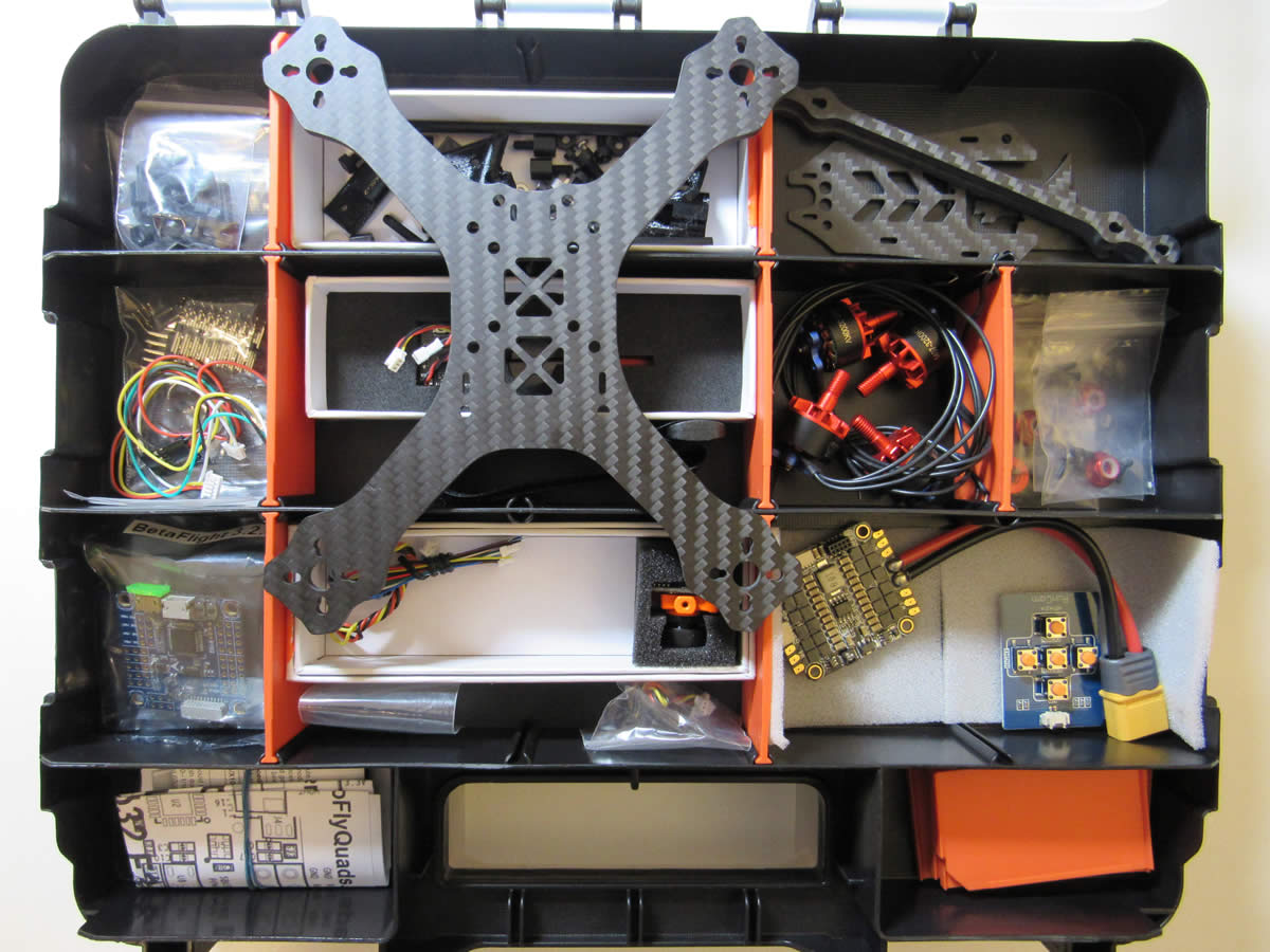
Unboxing
05 February 2018
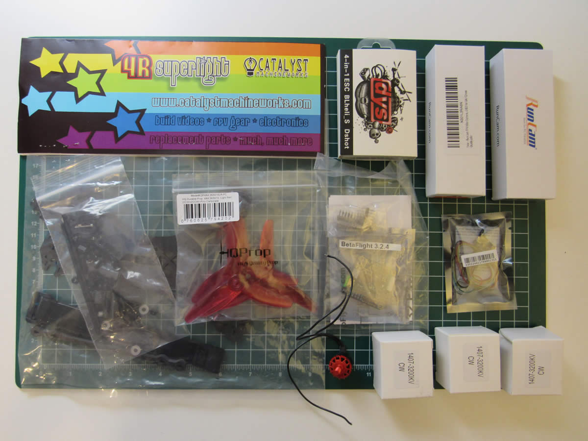
I have just about everything I need to start putting things together. Before I get ahead of myself, I plan on getting organized by staging parts in a compartmentalized box. This is a bit of a winter project, and I want to take my time. Yeah, right. Well, it's a plan anyway.
Notes:
- All clockwise motor thread build
- Catalyst Machineworks package came damaged, one of the motor boxes was totally crushed
First Impressions:
- This frame is high, high quality carbon fiber - They type you want to just pet
- 3D printed parts also seem to be of a very high quality
- *Kit was missing the aluminum standoffs, put a quick halt to my weekend project - CM sent out the standoffs immediately and I was back in business in a couple days!
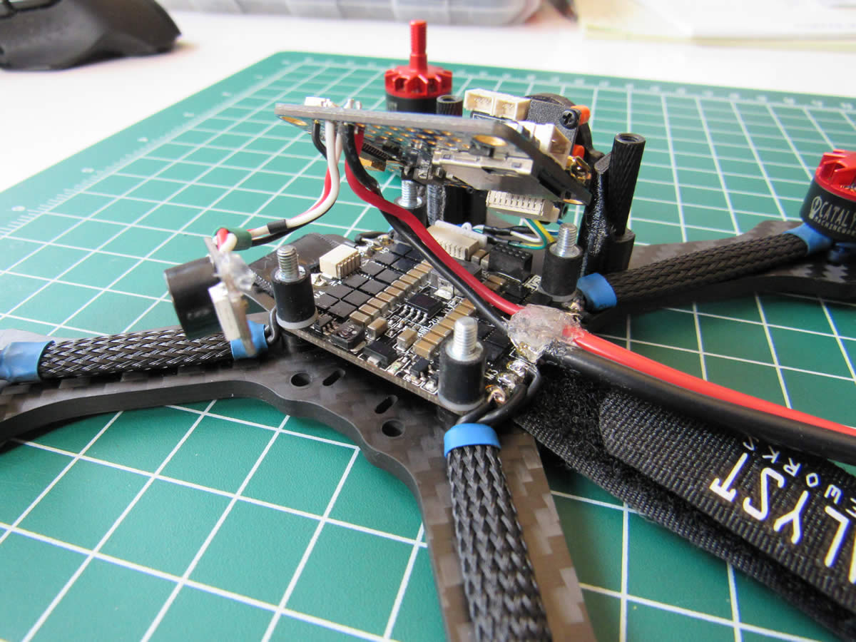
ESC Soldering
I am using an 4 in 1 ESC for this project. So much easier, and cleaner build wise. The only drawback to 4 in 1's is that if any one ESC on the board goes bad, you need to buy a new board. Such is life I suppose.
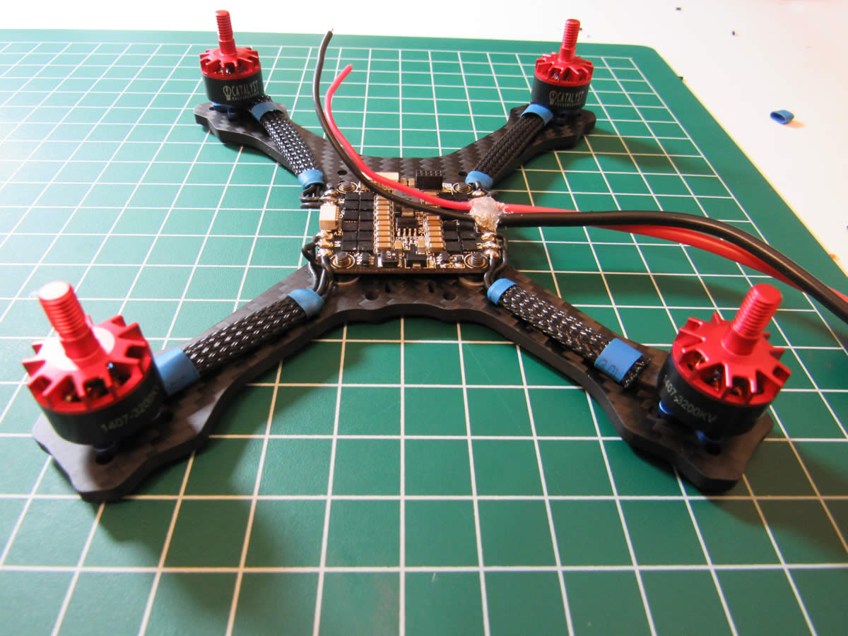
- Test mount motors and ESC Board
- Cut motor wires to required length
- Cut 4 30mm-34mm lengths of braided PE/Nylon wire sheath
- Pre-shrink some heat shrink tubing slightly on the ends of the wire sheath and feed the motor wires through one at a time
- Test fit motors and wires to prepare for soldering
- Solder all 4 motors to the ESC pads, the order of wiring is not important, you can reverse motors in the BLHeli Configurator
FC Power
I opted to power the flight controller directly from the battery. I basically just cabbaged on to the batt in pads on the ESC board.
- Remove ESC from the quadcopter
- Test fit the wires
- Cut the wires and give yourself enough slack so you can remove the flight controller to work on it as shown
- Solder two small wires on to the positive and negative solder joints on the ESC board where the power wires come in from the battery
- Apply some hot glue on top of the hot wires to prevent short circuits
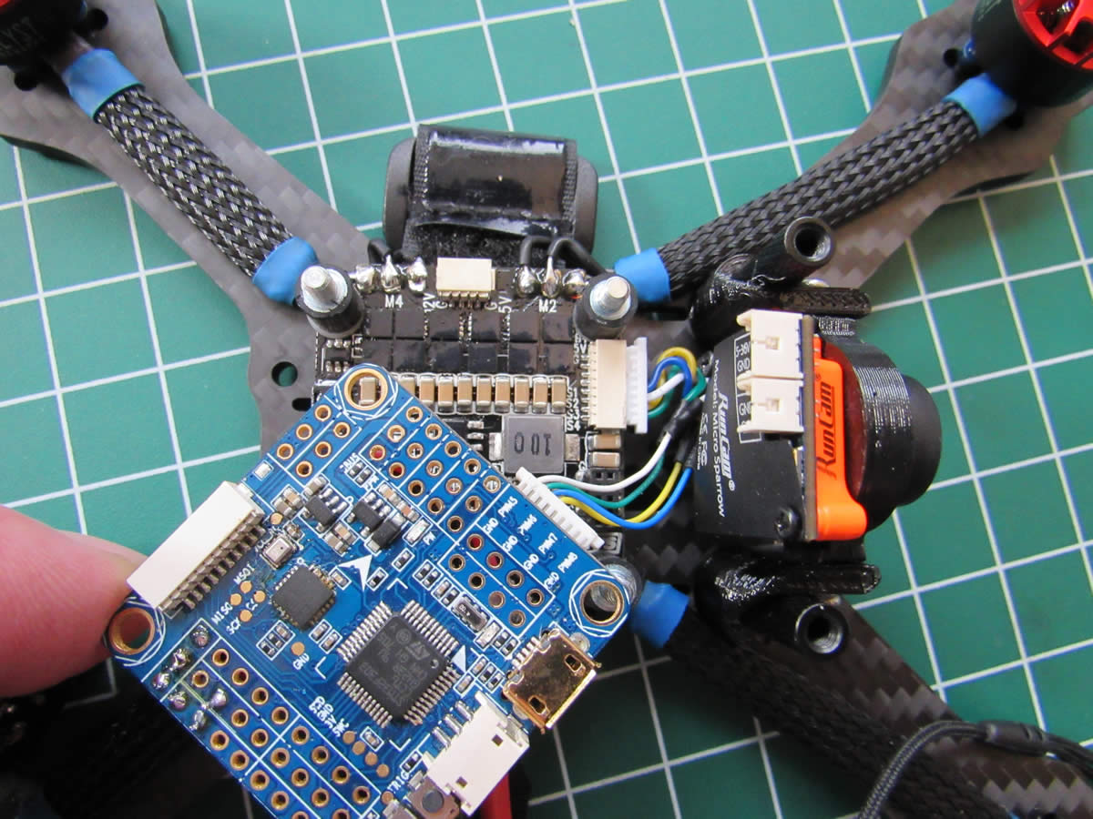
- Solder the positive wire to the VBAT pin on the FC, be careful not so use the VBAT pin below the RAM pin, this is a jumper
- Solder the negative wire to the GND pin next to the VBAT pin
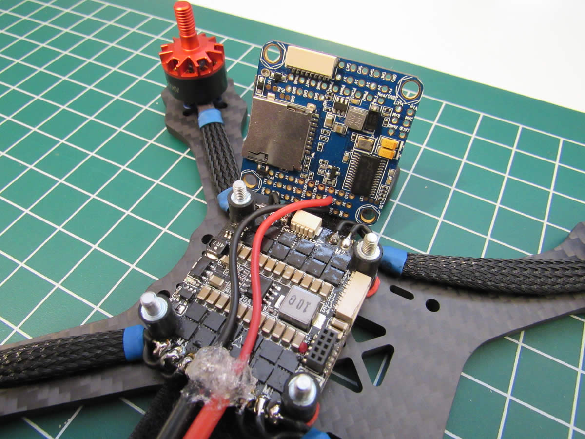
Connect ESC to FC
This particular setup has 1m, 8pin JST plugs that made wiring the ESC to the flight controller a snap.
- Make sure to plan out the motor routing, depending on your ESC orientation, you might need to map FC motor 1 to ESC motor 2 for instance
- Make a jumper using two 1m 8pin JST plugs, leave enough slack to easily plug and unplug the jumper
- Connect the flight controller to the ESC using the newly created plug wire combo
LED & Buzzer
I opted to go with a combo buzzer/led, pretty sweet!
- Solder the small wires that came with the LED board onto the board
- Test fit the LED board and cut the wires to length
- Solder the signal wire to the LED_STRIP pin on the FC
- Solder the positive wire to the 5V pin next to the LED_STRIP pin
- Solder the ground wire to the GND pin next to the 5V pin
- Solder the Buzzer negative wire to the BUZ- pin on the FC
Receiver
If you are using an F3 board, you can simply use the plug and wires that came with the R-XSR receiver. If you are using an F4 board, you will need to remove the yellow wire from the plug and solder it to the uninverted smart port pad on the R-XSR receiver.
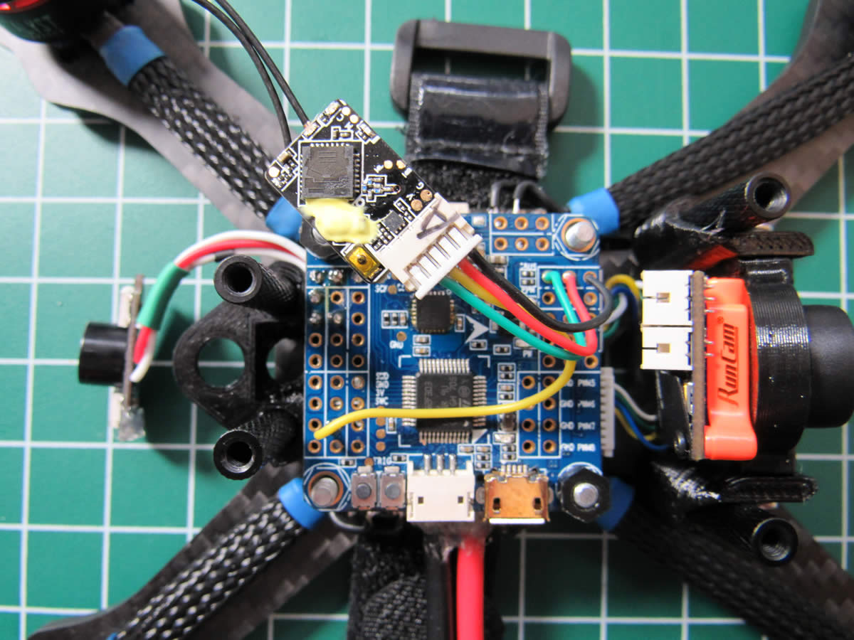
- Remove the yellow wire from the plug and solder it to the smart port pad on the receiver (If F4 board)
- Test fit the receiver and cut the wires to length
- Solder the yellow smart port wire to TX1 on the flight controller (UART1)
- Solder the SBUS signal wire to the signal pin on the PPM/SBUS row on the FC (UART6
- Solder the positive wire to the positive pin next to the signal wire
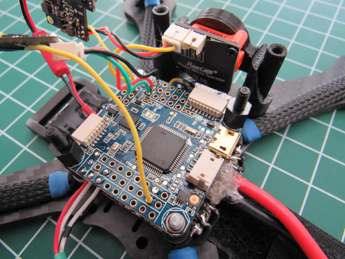
FPV Gear
Mounting the cam is pretty easy work, I didn't bother adding instructions for that. I opted to put a small LC filter in line to the VTX gear.
- Test fit the VTX transmitter
- Cut wires to length
- Solder the LC filter between the VTX power leads and the 4 pin JST plug which is the BEC out on the ESC, make sure to use the 5v positive and negative on that plug
- Remove the yellow wire from the plug that comes out of the VTX
- Place a new yellow wire in it's place, you need two if you want to have an OSD
- Solder the yellow wire that comes out of the camera to the VIN pin on the flight controller
- Solder the yellow wire that comes out of the VTX transmitter to the VOUT pin on the flight controller
Final Weight:
Dry: 178g
With 4s LiPo: 269g
I am not including any Betaflight configuration steps here. I set up this build with all the bells and whistles however!
Maiden Flight!
Build Updates
- 26 January 2018 - RunCam VTX and cam received from Amazon
- 31 January 2018 - Frame, motors, props and receiver ordered from Catalyst Machineworks
- 02 February 2018 - DYS 4 in 1 ESC received from Amazon
- 05 February 2018 - Frame, motors and flight controller received from CMW and Ready to Fly Quads
- 20 February 2018 - Wired up flight controller - Discovered bad OSD chip on board
- 04 March 2018 - Wired up second board, maiden flight success!
0 Comments